NEW
AUTOMATIC or MANUAL
BAND DECODER PCB
FROM SIX TO 160 METER
Hi, I started this project some years ago but due misbehavior from certain hams I do no longer publish the
schematics on my web page.
Their function and set up is explained in a few steps.
Completely tested boards are sold and starting 15/09/2005 I will be selling the PCB's & components also in Kit.
BLOCKDIAGRAM
" WHAT CAN IT DO FOR YOU ??"
A: Automaticaly select the correct ANTENNA & BANDPASSFILTER
with extensive galvanic isolation when the board gets data from :
1 - Band data out from YAESU tranceiver
2 - Band data out from ICOM tranceiver (For ICOM is a conversion board needed, works only on 10-15-20-30-40-80 & 160 Meter )
3 - DX4WIN via LPT port
4 - WRITELOG via LPT port
5 - ZS4TX SUPER COMBO KEYER (has a link through when only 1 LPT port is available)
6 - THE CT PROGRAM
7 - OTHER ham software programs that have the correct LPT data output available
B: Other available options are
1 - CW output from DX4WIN & WRITELOG software to tranceiver
2 - PTT output from DX4WIN & WRITELOG software to tranceiver
3 - SO2R PIN 14 link trough for 2 radio selection
C: Manual selection of the ANTENNA and related BPF
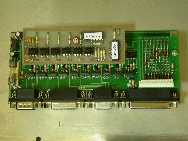
MAINBOARD PCB PHOTO
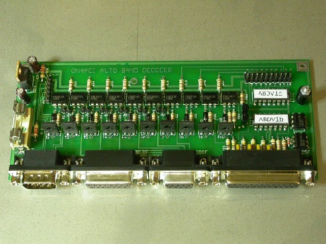
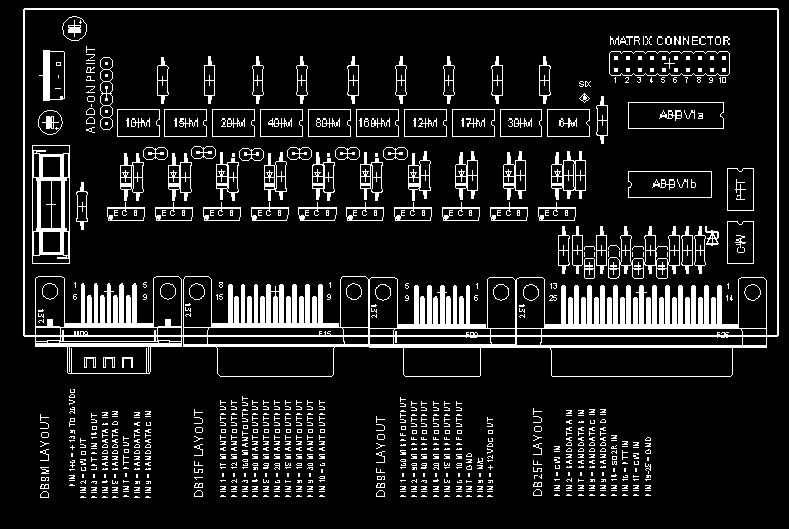
MAINBOARD-CONNECTIONS
Version 1 = Standard mainboard + Matrix board, full tested boards
- These boards are needed when you have ONLY MONOBAND Antennas
- The YAESU TRANCEIVER or PROGRAM sends DATA into the board and this AUTOMATICALY selects the correct Antenna and if
available the correct Band Pass Filter (DUNESTAR model 600 positive keying or equivalent).
- For correct operation pin 1-2-7-8-9-14-16-17 and 18 to 25 are used from the DB25 female connector
- Standard straight cables can be used when hooked up to the computers LPT port and the BPF DB9 input connector
- The 10 BANDS have there own HIGH current output via DB15 female connector
- Also a 10-15-20-40-80-160 LOW current (150 mA) BPF output via DB9 female connector
- galvanic isolated CW output controlled by DX4WIN & / or WRITELOG software on pin 2 from DB9 Male connector
- galvanic isolated PTT output controlled by DX4WIN & / or WRITELOG software on pin 7 from DB9 Male connector
- SO2R PIN 14 link trough on pin 3 from DB9 Male connector.
- 12 position switch for "OFF - AUTOMATICALY or MANUALY OPERATION" selection.
Version 2 = "STARTING 15-09-2005" Standard mainboard + Matrix board = 2PCB's + All components in Kit
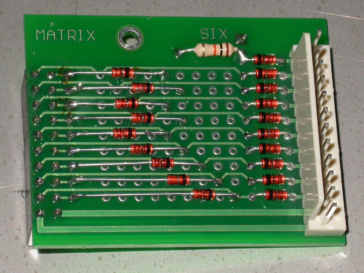
MATRIX FOR MONOBAND ANTENNAS
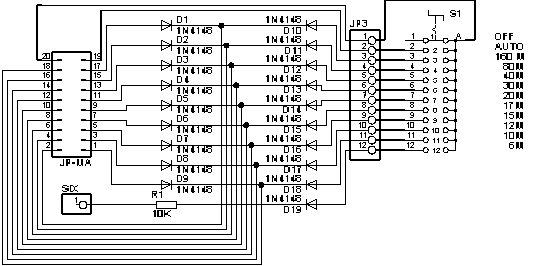
MATRIX PCB

Version 3 = Standard mainboard + ADD-ON board + Matrix board, full tested boards
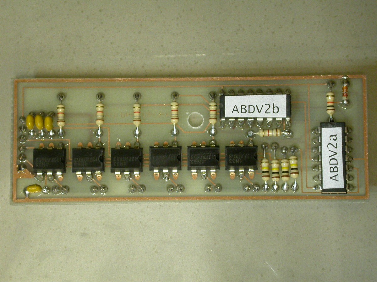
ADD-ON BOARD
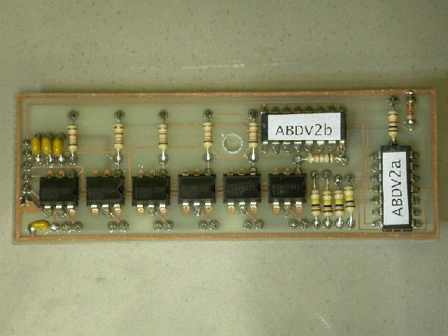
- This ADD-ON board must be used when you have combined Antennas (beams) and also Band Pass Filters.
- The 12 possition switch should be put in AUTO mode for correct operation.
- EXAMPLE of a station setup
- Following Antennas are available, 6 M beam, 10-15-20 M Beam, 40 M dipool, 80 M Vertical,
- 12-17-30 M Beam and a 160 M vertical
- The combination for the beams is done on the MATRIX board with small diodes
- The YAESU TRANCEIVER or PROGRAM sends DATA into the board and this AUTOMATICALY selects the correct Antenna or BEAM
- and also switch the correct Band Pass Filter IN.
- All 10 BANDS output are also via the DB15 female connector
- BUT due the BEAMS the output pins from the DB15 Female connector are different now !!!
- 160 M, 80 M , 40 M & 6 M remain on the normal output pins,
- since commercial BEAMS have normaly only one connection the bands are combined on one output now,
- so the output for 12-17 & 30 M BEAM is on the 30 M pin and for the 10-15 & 20 M BEAM on the 20 M pin !!!
- CORRECT Band Pass Filter for 10-15-20-40-80-160 M band output on the DB9 female connector
- galvanic isolated CW output controlled by DX4WIN & / or WRITELOG software on pin 2 from DB9 Male connector
- galvanic isolated PTT output controlled by DX4WIN & / or WRITELOG software on pin 7 from DB9 Male connector
- SO2R PIN 14 link trough on pin 3 from DB9 Male connector
- With the 12 possition switch you can also MANUALY select the ANTENNAS
- BUT NO BAND PASS FILTER OUTPUT IS AVAILABLE WHEN YOU SELECT MANUAL THE ANTENNA !!!!!
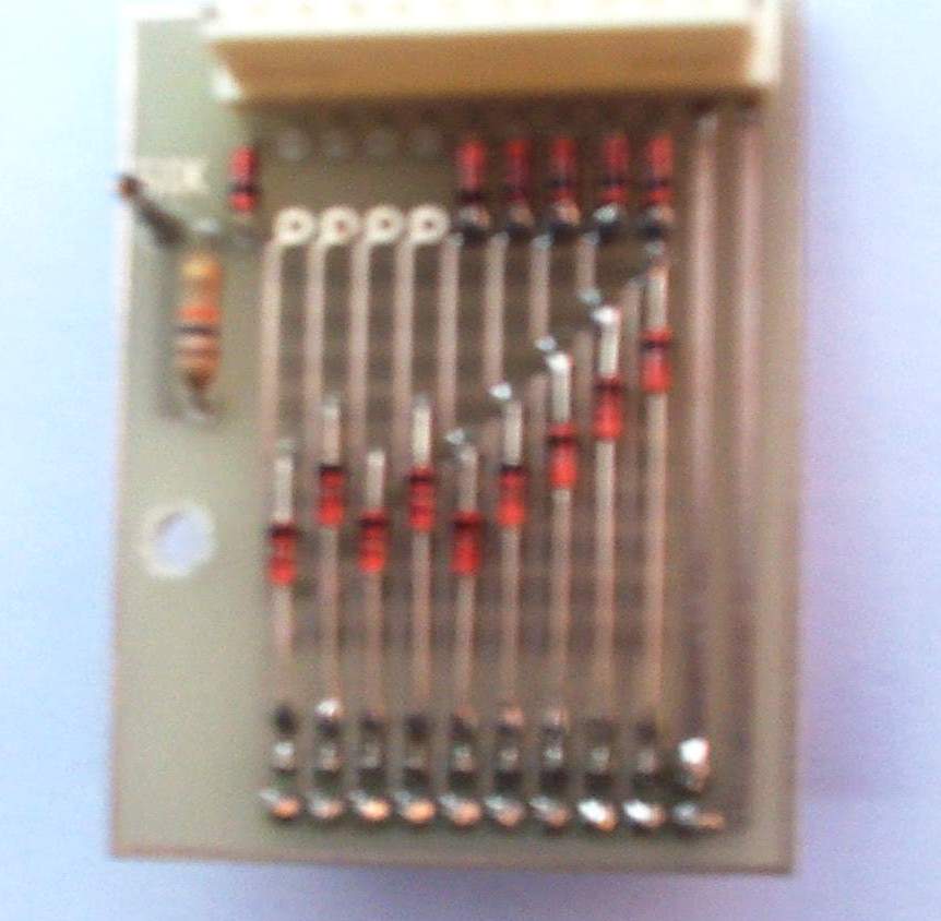
MATRIX FOR ABOVE EXAMPLE
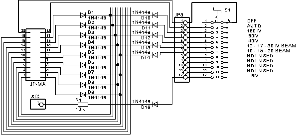
MATRIX BOARD FOR EXAMPLE

Version 4 = Standard mainboard + ADD-ON board + Matrix board = 3PCB's + All components in Kit
Ask for prizes and shipping cost, this depends on how you like it
FULL OPTION PCB
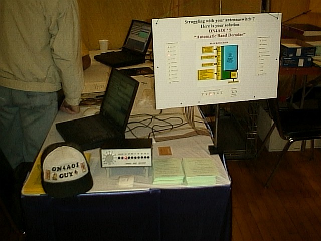
DAYTON2002 setup @ the DX4WINBOOT
LICENSED DX4WIN USERS GET A 10% REBAT
STARTING 06-01-2003 PAYMENT IS ACCEPTED VIA PAYPAL (ADD 4% TO TOTAL)
Pay me securely with any major credit card through PayPal!
GUY ON4AOI
COMMENTS ARE WELCOME